134-22 Main Wiring Diagram
UNDERSTANDING TOYOTA WIRING DIAGRAMS WORKSHEET 1 1. MAZDA WIRING DIAGRAMS WORKSHEET 1 1.

Qs For The Dynamic Metabolic Control In Gram Negative Bacteria A Download Scientific Diagram
GENERALGENERAL ELECTRICAL CONNECTION DIAGRAMSACME TRANSFORMER WIRING DIAGRAMS PRIMARY.

134-22 main wiring diagram. In the sub-panel box the neutral and ground wires will connect the same as they do in the main breaker box but the red and black wires will connect to the hot bar instead of. There are many different ways to look at fixing an electrical problem but we will stick with the easiest way. CIRCUIT FUNCTIONS All circuits in the diagrams use an alphanumeric code to identify the wire and its function.
None X4X1 H4 H3 H2 H1 X2X3 PRIMARY. For example a home builder will want to confirm the physical location of electrical outlets and light fixtures using a wiring diagram to avoid costly mistakes and building code. Trace the wiring till you can see where a short may have taken place.
Describe and identify the F in diagram component S. As you are into the workspace of EdrawMax drag the symbol that you need directly onto the canvas. Basics 10 480 V Pump Schematic.
Describe the meaning of the G-W in diagram component R. Describe and identify the diagram component Q. Basics 11 MOV Schematic with Block included Basics 12 12-208 VAC Panel Diagram.
Describe the meaning of the dotted line in the diagram component P. Basics 7 416 kV 3-Line Diagram. An extensive collection of electrical diagram templates can be found in the Electrical Engineering category.
Green or bare wire is the ground wire. Obviously on any given project it is. - nent layout Wiring diagram Weight Indicator actuator Front dimension 18 x 18 mm 1 Universal 20 x 05 mm 31-703006 4 1 0006 kg 2 Universal 20 x 05 mm 31-704006 4 2 0006 kg Solder 28 x 05 mm 31-050002 3 0004 kg Solder 31-050005 3 0004 kg Universal 20 x 05 mm 31-051006 4 3 0005 kg.
B Transmission Line Standards Aerial Patrol Warning Signs and Marker Ball Marking Diagrams 130. To identify which circuit code applies to a system refer to the Circuit Identification Code Chart. Basics 13 Valve Limit Switch Legend.
Describe and identify the diagram component T. Describe and identify the RB in diagram component R. C Transmission Line Structure Standards Steel Pole Structures Maintenance Provisions Work Ring.
Select one wiring diagram template to edit on. Basics 8 AOV Elementary Block Diagram. Open EdrawMax desktop software or EdrawMax web-based application.
The purpose of this document is to propose a technical solution based on SOCOMEC motorised changeovers and switches to answer the greatest number of standard ATS diagrams made with others technologies. White wire or off-white is neutral. In the above diagram I have shown the complete method of wiring I wired an energy meter after that a double pole and then single pole breakers for each room or each point of circuit load.
Describe the meaning of the C13 in the diagram component Q. 48 Residential wiring diagram 50 Overview of the installation and related wiring accessories standard 52 Consumer units Din-Rail equipment by Legrand Group. You can resize the selected symbol by dragging the selection.
2 - TRANSFER BETWEEN 2 SOURCES - 1 Bus bar - TRANSFER BETWEEN 2 SOURCES - 2 Bus bars - TRANSFER BETWEEN 2 SOURCES - 3 Bus bars -. Describe the meaning of the SD in diagram component T. Using EdrawMax to create your own wiring diagram.
Describe the meaning of the 2 in diagram component S. Find out how to access AutoZones Main Wiring Diagram Equivalent To Standard Equipment Cabrio 1999 1999 Repair Guide for Volkswagen Cars 2000-05. Basics 14 AOV Schematic with Block included Basics 15 Wiring or Connection.
120240 2 2 12 ANFC 4 2 2 BNFC X4 X1 H10 H2 H3 H1 X2 X3 H5 H6 H4 H7 H8 H9 ConnectConnect Primary Primary Inter- Secondary Volts Lines To Connect. Navigate to New Electrical Engineering Basic Electrical Step 3. Inside the covering youll find a copper wire the ground wire a white covered wire the neutral wire a black wire the hot wire and a red wire another hot wire.
Sets of wiring rules showing the main technical characteristics of each set of installation and main accessories standards. Main lugs and main circuit breaker load centers have wire binding screw torque values on the wiring diagrams and circuit breaker labels Neutral Assemblies All lugs suitable for copper or aluminum wire see Main Lugs and Main Circuit Breaker Ratings on page 20 Branch neutral terminals suitable for one 144 AWG copper or one. 240 X 480 SECONDARY.
The individual wires on the diagram should be colored the same as the actual wires you will be using. Each wire shown in the diagrams contains a code which identifies the main circuit part of the main circuit gage of wire and color Fig. 41 9030 Transmission Line Standards Light Duty Steel Pole H-Frames Structure Signs Details and Locations 131.
Volkswagen Cars 2000-05 Main Wiring Diagram Cabrio 1999 1999 Repair Guide. Highlight the individual circuit using a different color for positive and negative. DIY enthusiasts use wiring diagrams but they are also common in home building and auto repair.
They are also useful for making repairs. Basics 9 416 kV Pump Schematic. Click the icon of Basic Electrical to open the library that includes all symbols for making electrical diagrams.
Electrical switch diagrams that are in color have an advantage over ones that are black and white only. First find the problem area on the wiring diagram. Describe and identify the diagram component U.
Thats why we can call him the main circuit breaker box. Use wiring diagrams to assist in building or manufacturing the circuit or electronic device. 240 X 480 SECONDARY.
The main reason for this board in E wiring is that we can control the complete wiring from this place.

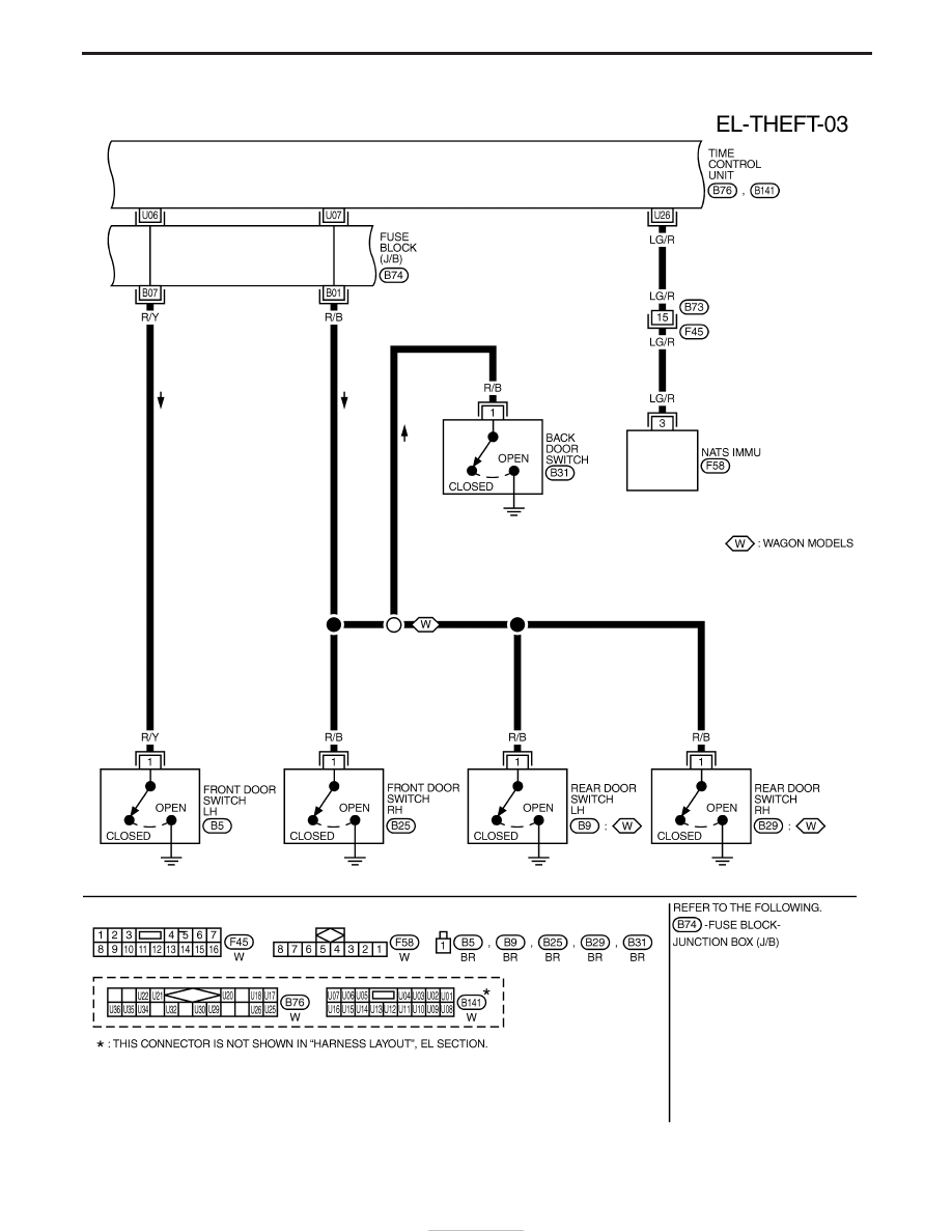
Nissan Terrano Model R20 Series 2004 Manual Part 436

Informasi Gedung Vinilon Building Official Web

Electronics Circuit Circuit Diagram Electronics Components

Komatsu Bulldozer D68ess 12 Power Train And Final Drive

Nissan Terrano Model R20 Series 2004 Manual Part 436

Gm Oem Eletrico Fusivel Capa Superior Caixa De Rele 15278531 Ebay
Jc18003373 Weighfeeder Complete Manual Electric Motor Hazards

Nissan Terrano Model R20 Series 2004 Manual Part 436

Electronics Circuit Circuit Diagram Electronics Components
Jc18003373 Weighfeeder Complete Manual Electric Motor Hazards

Nissan Terrano Model R20 Series 2004 Manual Part 436
1twd026202n0101 Electrical Wiring Electricity

Komatsu Bulldozer D68ess 12 Power Train And Final Drive

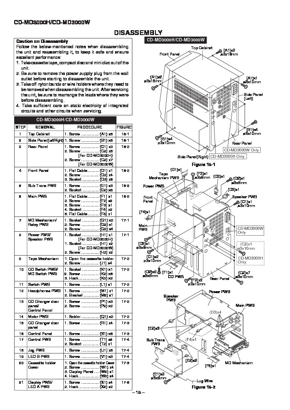
Sharp Cd Md3000 Serv Man14 Service Manual View Online Or Download Repair Manual Pcb Layout 1

Electronics Circuit Circuit Diagram Electronics Components

Komatsu Bulldozer D68ess 12 Power Train And Final Drive

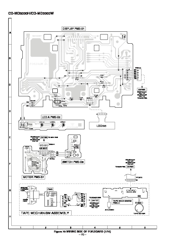
Sharp Cd Md3000 Serv Man14 Service Manual View Online Or Download Repair Manual Pcb Layout 1


