1734-8cfg Wiring Diagram
To enter Filter values from 3276865535 s use this conversion formula. Wiring Diagram For Jakel Power Vent 110533 On Bradford White Water Heater.
Https Www Prosoft Technology Com Prosoft Download 9113 169901 Version 17 File Ilx34 Mbs Um Pdf
Desired Filter Value in s - 65536 Entered Filter Value in s.
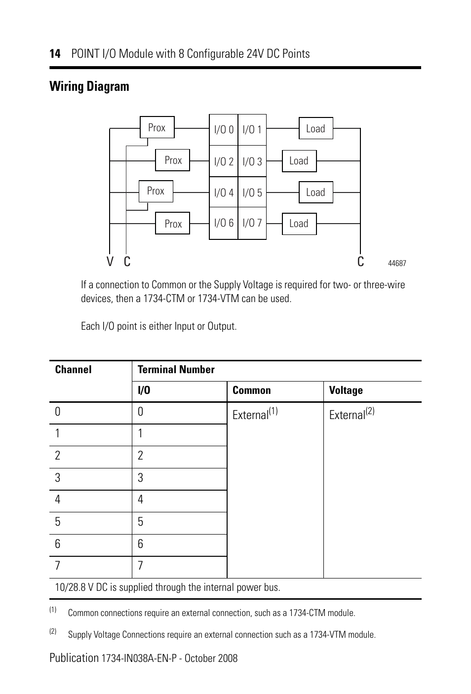
1734-8cfg wiring diagram. Assembly The 1734-TB or 1734-TBS wiring base assembly consists of a 1734-MB mounting base and a 1734-RTB or 1734-RTBS removable terminal block RTB. 1734 ib8s manual pdf. The 1734-8CFG module is a 24V DC IO module with eight self-configuring points.
Figure 34 Ground Jumper Locations for the 5 and 10 kW System Modules 1394- SJT xx- x. The module supports removal and insertion under power auto-address and auto-baud in. Comprehensive diagnostics and configurable features make POINT IO.
1734-TBS 1734-TB3S 1734-RTBS 1734-RTB3S POINT IO Removable Terminal Block Installation. The Allen-Bradley CFG is a POINT IO DC Configurable IO with the TOPS TOP TBS and the TB wiring base units. V and V need two wires to complete circuit plus ground wire for safety.
A wiring diagram is often used to troubleshoot problems and to create distinct that all the associates have been made and that all is present. You can mix standard and safety IO in the same system. The 1734-8CFG module is a 24V DC IO module with 8 self-configuring points.
Each of the IO points can be a DC input or output. Wiring base assembly POINT IO Cold Junction Compensation Wiring Base Assembly 1734-IN583 POINT IO wiring base assembly POINT IO Wiring Base Assembly Installation Instructions 1734--IN013 Very high speed counter module POINT IO 24V dc Very High Speed Counter Module 1734-IN003 POINT IO 5V dc Very High Speed Counter Module 1734-IN004. Locking plug Wiring diagrams.
Freightliner Century Class Fuse Diagram. He2 Molecular Orbital Diagram. 2006 Polaris Phoenix 200 Wiring Diagram.
RSLogix 5000 software supports the signed Integer data type INT -3276832767 range. Wiring System Axis and Shunt Modules and Motors for all systems 4. Plot Diagram For Where The Red Fern Grows.
POINT IO and ArmorPOINT IO DeviceLogix Modules User Manual Looking for more. 1734 -485ASC POINT IO ASCII User Manual. Nema L14 4-pole is Resources.
Locate the ground jumper inside the system module. 04122018 04122018 6 Comments on 1734-8cfg Wiring Diagram Description. Receptacle so youre making a NEMA P to NEMA LR adapter.
1734 -8CFG POINT IO Module with 8 Configurable 24V DC Points IN. Wiring Diagram For Aerator Pump In Jon Boat. 1734-TB 1734-TBS POINT IO Removable Terminal Block Installation Download.
1734-TB -TBS -TB3 and -TB3S Specifications Out 0 Out 1 Out 1 Out 0 CC V V Load Load 42014 V 1224V dc C Common Field power is supplied from power. Interconnecting wire routes may be shown approximately where particular. 1734 -8CFGDLX POINT IO Module with 8.
Rockwell Automation CFG POINT IO Module with 8 Configurable 24V DC Points IN equipment and hard-wired electromechanical devices. The 1734-8CFGDLX module is an 8-point 24V DC IO module with 8 self-configuring points and DeviceLogix capabilities. Go to Grounding Your 1394 System.
1734 -485ASC POINT IO RS-232 and RS-485 ASCII Modules Installation Instructions. View and Download Rockwell Automation 1734-8CFGDLX POINT IO Module with 8 Configurable 24V DC Points and DeviceLogix IN instruction manual online. The module supports removal and insertion under power auto-address and auto-baud in compliance with the POINTBus backplane.
1734-TB or 1734-TBS POINT IO two-piece terminal base which includes the 1734-RTB Removable Terminal Block. Close the system module door. Use this diagram to identify the external features of the module.
Resource Description ArmorPOINT IO DeviceLogix Module ArmorPOINT IO Modules with 8 Configurable 24V DC Points Wiring Provides wiring diagrams for 1738-8CFGDLXM8 Diagrams publication 1738-WD009 1738-8CFGDLXM12 and 1738-8CFGDLXM23. V requires 1 hot. Install POINT IO DeviceLogix Modules The 1734-8CFGDLX is compatible with 1734-TB 1734-TBS 1734-TOP and Install the Mounting Base 1734-TOPS wiring bases.
Allen-Bradley 1734-AENT EtherNetIP Twisted Pair Media IO Adapter 24V DC Series A 10612598290434 UPP Ser A. Assuming your amp is happy at v and is wired per Yoels diagram. Our Bulletin 1734 POINT IO modules offer digital analog and specialty IO as well as POINT Guard safety-rated IO with one to eight points per module.
1734-8CFGDLX Installation Use your product. Before You Begin See the figures to familiarize yourself with major parts of the module noting. 95 1734 Point IO Installation Instructions.
Refer to the figure below for jumper location. Each of the IO points can be a DC input or output. Each of the IO points can be a DC input or output.
As an example for a 40 ms filter time 40000 - 65536 -25536. Note that the wiring base assembly consists of one of the following. POINT IO 3 Publication 1734-IN510B-EN-P - August 2000 Wiring Diagrams Specifications General specifications - These specifications are shared by all components of the 1734 POINT IO system.
The module supports removal and insertion under power auto-address and auto-baud in compliance with the POINTBus backplane. Architectural wiring diagrams put it on the approximate locations and interconnections of receptacles lighting and enduring electrical facilities in a building. Nema L6 is same configuration for 20P or 30 P use for 15 20 30 amp.

Rockwell Automation Allen Bradley Point I O Devicelogix User Manual Pdf Download Manualslib

Point Io 1734 Allen Bradley Input Sensor Hardware Installation Wiring Testing Programming Tutorial
Http Literature Rockwellautomation Com Idc Groups Literature Documents Rn 1734 Rn017 En E Pdf
Http Www Simplying Com Pdf 1734 Pdf
Http Www Simplying Com Pdf 1734 Pdf
Http Literature Rockwellautomation Com Idc Groups Literature Documents In 1734 In041 En P Pdf

Pin On All Used Cars
Http Www Simplying Com Pdf 1734 Pdf

How To Wire In A Starer Button On Glow Plugs On A 7 3 Idi In 2021 Wiring Diagram Diagram Relay
Http Www Simplying Com Pdf 1734 Pdf

Point Io 1734 Allen Bradley Input Sensor Hardware Installation Wiring Testing Programming Tutorial
Http Literature Rockwellautomation Com Idc Groups Literature Documents At Safety At108 En P Pdf

Wiring Diagram Rockwell Automation 1734 8cfg Point I O Module With 8 Configurable 24v Dc Points In User Manual Page 14 24 Original Mode

Point Io 1734 Allen Bradley Input Sensor Hardware Installation Wiring Testing Programming Tutorial
Rockwell Automation 1734 8cfg Point I O Module With 8 Configurable 24v Dc Points In User Manual 24 Pages
Http Www Simplying Com Pdf 1734 Pdf

How To Wire In A Starer Button On Glow Plugs On A 7 3 Idi In 2021 Wiring Diagram Plugs Diagram
Https Literature Rockwellautomation Com Idc Groups Literature Documents Um 1734 Um017 En E Pdf