Honeywell Fan Limit Control Wiring Diagram
Diagram Honeywell Fan Control Center Wiring Full Version Hd Quality Roofstructuredeicing Ld Rose Fr 90 113 White Rodgers Fan Control Center Arnold S Service Pany Inc Diagram Wiring Fan Control Center Full Version Hd Quality Welderwiring1d Sentierimeridiani It. 1416 or 18 solid wire or Nos.
Wiring Diagram Relay Control

Honeywell Fan Center Wiring Diagram inside Honeywell Fan Limit Switch Wiring Diagram image size 1023 X 571 px and to view image details please click the image.
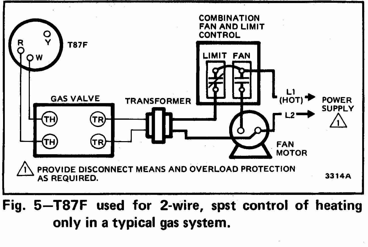
Honeywell fan limit control wiring diagram. Fan and Limit Controls Key features for the family of universal fan and limits. Honeywell fan limit switch wiring diagram Architectural circuitry representations reveal the approximate areas and affiliations of receptacles lights as well as long-term electric solutions in a building. Combination fan and limit furnace control time assist closes fan opens limit circuit on temp rise.
The following is a wiring diagram for a Honeywell Fan Limit Switch Control. On Honeywell 3 Speed Fan 14f0 Wiring Diagram. Honeywell Fan Limit Control And Wiring Wiring Diagram A wiring diagram is a type of schematic which utilizes abstract photographic signs to show all the affiliations of elements in a system.
It shows the parts of the circuit as streamlined shapes and the power as well as signal connections in between the gadgets. A wiring diagram generally gives details about the relative setting and plan of. Variety of honeywell fan limit switch wiring diagram.
Collection of honeywell fan limit switch wiring diagram. 100 to 250f limit rng. Please download these honeywell fan limit switch wiring diagram by using the download button or right click on selected image then use Save Image menu.
Honeywell Fan Limit Control And Wiring Example Wiring Diagram Super tradeline l4064b universal combination fan and limit controllers applica tion the l4064b controls the on and of f operation of the heating unito s fan motor and provides high limit control of the main burner. It shows the elements of the circuit as streamlined shapes and the power and also signal connections in between the devices. It reveals the components of the circuit as simplified shapes and the power and signal links between the devices.
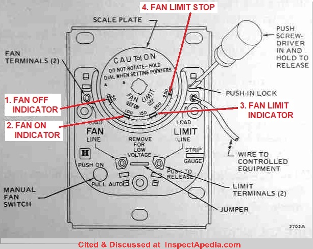
It shows the elements of the circuit as streamlined shapes and also the power and signal links in between the gadgets. I explain the heat operated Honeywell fan and limit switch used on early gas furnaces. Load voltage to the fan is wired at the upper left push-in terminal.
Wiring Connections When connecting cable or conduit to this controller use care to avoid strain on the control case. Male flag connectors on both the fan and limit switches Fig. Interconnecting cord courses may be revealed about where certain receptacles or fixtures have to be on a common circuit.
How To Install And Wire The Honeywell L4064B Combination Furnace intended for Honeywell Fan Limit Switch Wiring Diagram image size 800 X 600 px and to view image details please click the. Honeywell L4064b Combination Fan And Limit Control How To Set The Temperatures Limits On Furnace Switch. Strip insulation from wires the distance shown by the strip gauge on the controller.
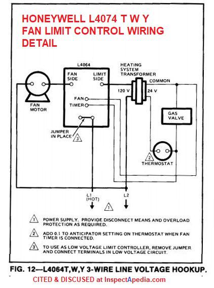
64 mm male flag connectors on both the fan and limit switches Fig. A wiring diagram is a simplified traditional pictorial depiction of an electric circuit. Wiring Diagram for L4064.
Collection of honeywell limit switch wiring diagram. Connections can be made to standard wire push-in terminals or female receptacles for 14 in. For Standard wire Push-in terminals.
14 or 16 stranded wire depending on electrical requirement. This video is part of the heating and cooling series of training vide. I think once the fan on mode is selected it breaks the feed from the fan side of the fanlimit control.
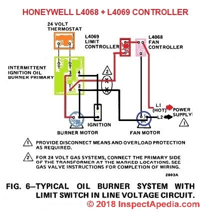
Universal Combination Fan and Limit Controllers heating units fan motor and provides high limit control of the main The LB has a manual switch to provide on the product to make sure the product is suitable for your application. Honeywell RM oil primary control 40 VA transformer powers control circuit mounts on a 4 x 4 junction box burner housing or appliance cabinet used with 24V thermostat. As Honeywells illustration shows the two fan terminals are on the upper and lower left side of the control.
Family members cover the full range of insertion 5 8 11-12 Adjustment tool and cross-reference allow for field adjustment to factory settings Universal kit accessories reduce inventory L4064 High Limit and Fan Controller. August 9 2018. Assortment of honeywell fan limit switch wiring diagram you can download for free.
Furnace fan switch wiring diagram. Replaces RM and White Rodgers and page 1. Honeywell fan and limit control 8 insertion.
Relay switch instructions rgf control circuits for air conditioning furnace fan limit honeywell relays wiring diagrams understanding with the 90 340 ac diagram hyundai radiator fans hvac full ford center generic 120v coil 02 windstar fuse mobile home coleman er a factory. A wiring diagram normally provides. Wiring diagrams help technicians to find out how the controls are wired to the system.
Wiring Diagrams - Honeywell Temperature Fan Limit Switch. A wiring diagram is a simplified standard pictorial depiction of an electric circuit. March 8 2018 by headcontrolsystem.
Turn the power off at the furnace and go a step further for safety and turn the power off at the breaker. Before beginning any wiring make sure you turn the power off. A wiring diagram is a streamlined standard pictorial representation of an electric circuit.
FOR ST ANDARD WIRE PUSH-IN TERMINALS Connect wires to the terminals as follows. 200f stop set 50-200 fan off. Line voltage is wired at the bottom left push-in terminal.

Fan Limit Control Installation Faqs
Diagram Honeywell Fan Center Control Wiring Diagram Full Version Hd Quality Wiring Diagram Trudiagram Amicideidisabilionlus It
Fan Limit Control Installation Faqs

Fan Limit Switch Background Troubleshooting Heat Cool Plumb

Honeywell Temperature Fan Limit Switch Quality 101

Wiring Diagram Connecting Honeywell Humidifier To Carrier Furnace Bright Electric Furnace Thermostat Wiring Furnace

Motor Control Center Schematic Diagram Control Center Schematic Design Diagram
Honeywell L4064b Combination Fan And Limit Control How To Set The Temperatures And Limits On The Furnace Fan Limit Switch Control
Diagram Furnace Fan Limit Control Wiring Diagram Full Version Hd Quality Wiring Diagram Veediagram Amicideidisabilionlus It


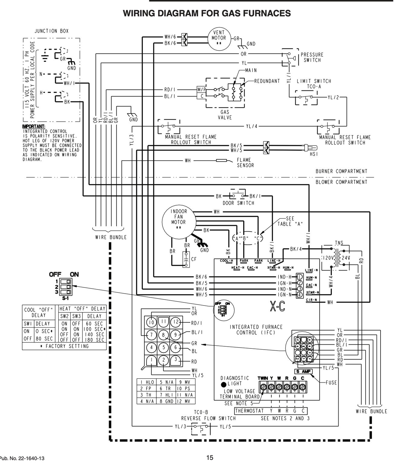
Wiring Diagram For Furnace Gas Valve Inspirationa Ecobee Wiring Diagram Volovetsfo Wiring Diagram Diagram Thermostat Installation
How To Install Wire The Fan Limit Controls On Furnaces Honeywell L4064b All White Rodgers Fan Limit Controllers

Honeywell Temperature Fan Limit Switch Quality 101

Basic Hvac Control Wiring Schema Wiring Diagram From Control Wiring Source 18 Shjj Raphae Electrical Circuit Diagram Basic Electrical Wiring Thermostat Wiring

L6064 Fan Limit Control Doityourself Com Community Forums
How To Install Wire The Fan Limit Controls On Furnaces Honeywell L4064b All White Rodgers Fan Limit Controllers
Fan Limit Switch Q A 5 Furnace Fan Limit Control Troubleshooting
Diagram Baseboard Heater Control Wiring Diagram Full Version Hd Quality Wiring Diagram Diagrammar Prolococusanese It

New Wiring Diagram For Central Heating Programmer Diagram Diagramtemplate Diagramsample Check More At Https Servisi Co Wiring Diagram For Central Heating P

Pin On Vic